Overview
General
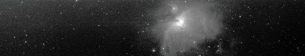
Images
with short focal length
Images
with long focal length
How to
take a drift scan image
Differential trailing
Possible problems
Accuracy of the timer
Astrometry
Using
WinScan or SCAN for observing occultation's:
Other
applications for WinScan or SCAN
Using
WinScan or SCAN to take speckle images:
Download
Links
Some
drift scan images
E-mail: web1@driftscan.com
The lines of the CCD will be read out with the same speed, as the
picture of the star moves over the CCD. (TDI = Time Delay
Integration)
Animation
The telescope is not moved. The time to read out a line (shiftime) can be calculated by the focal length,
the declination, the height of the pixels and the siderial rate.
See an example algorithm in C++: PIXSEC.TXT
Example: Focal length 750 mm, pixel height 9 um, declination 20 degree= 0,175122 seconds to read out a line.
If you are using for example a ST-7 and a photo lens with 50mm FL (focal length) you will get an effective exposure time of 1258 sec.
(The time, the star needs to move across the CCD.) Because of that long exposure time the CCD will become saturated. Even if you stop down the lens,
or if you use filters, there may be problems as the orientation of the camera must be very exact, the focal length must be well known,
the CCD must point to 0° declination, the image must not have distortions caused by the lens. You may get problems with trailing,
the stars become trails or will look elongated.
You may use the partial TDI mode to avoid that.
Check stardial:
Stardial
(extern link)
You will take many images, instead of one long stripe.
Taking such an image the shutter opens, the exposure is started, and
the CCD is read out line after line at sidereal rate, but after about 25
lines, the shutter is closed, and the CCD is read out complete.
The effective exposure decreases to 1285*25/510= 61 sec.
Differential trailing will be reduced
You may use WinScan to take partial TDI images. Partial TDI images will be useful for example to search for variable stars.
To search for asteroids you need a pixel scale of about < 2.5 arc sec (> 750 mm FL when using a ST-7).
Using more then about 300 mm FL, long stripes can be read in. (about this I will write now)
The files can be very big. The effective exposure time is
calculated: number of the lines * the time to read out one line.
Example : ST-7, 750 mm FL declination 20 degree , 0.175122 seconds to read out a line: 510 * 0.175122 = 89.3 sec. The effective exposure time is 89.3 seconds.
The possible read out speed is in most cases height enough. Example: ST-7, a Pentium II computer at 233 MHz , shortest possible shiftime 0.027 sec,
possible FL up to 4166 mm. The ST-8 needs about twice the time to read a line, so you can use a telescope up to about 2000 mm focal length.
A faster computer will decrease the shortest possible shiftime a little. The new cameras with USB interface will be also faster. Make some tests,
if you want to use a long FL.
Details
about the readout speed
With long focal length the effective exposure time decreases. The field of view also decreases. The array disks caused by seeing will become bigger.
So a shorter focal length should be preferred (fast scope). (To search for asteroids, the pixel size should be about 2.5 arc sec) I am using 750 mm.
With long focal length you will get big files in a short time. For example: . ST-7, 750 mm FL about 33 MB in one hour, with 2000 mm FL about 89 MB
in one hour.
With binning the resolution can be decreased, the field of view is smaller as it is using a shorter focal length and no binning.
The orientation of the camera is very important! The picture of the star moves parallel to the columns.
Using CCDOPS form SBIG
a star moves , comparing one image with the next , form the
bottom of the screen to the top.
I am using a telescope, 6 inch newton, 751 mm focal length, Vixen, GP mount. First I look for the polar alignment. The telescope should be put outside some time before using it, because the focus will change, when the temperature is changing (The focal length may change also). Then the CCD camera will be attached. I am using a ST-7 from SBIG , 510x765 Pixel, 9 um (micrometer) pixel. I added a self build attachment, so the orientation of the camera can be adjusted by a screw. CCD-Camera Then I focus the camera using CCDOPS. (peak value method) (WinScan has a fast focus feature, see the help file) I build a micrometer screw at my telescope to adjust the exact focus. Focusing without a mount will be a little more difficult. Then I control the orientation. If the camera is in the right orientation, a star moves, at shut of telescope drive, form the bottom(east) to the top(west) of the image(screen) (using CCDOPS). To adjust the orientation exact, I take an image with trails of the stars using CCDOPS (Turn off the clock drive of the telescope). I am using an exposure time, a little shorter than the time a star needs to move from the bottom to the top of the image, so the ends of the trails are visible.(about 60 sec) A trail of a star should be exact at one column. That can be checked, using the X-Hairs of CCDOPS. Trails. If necessary I rotate the camera carefully. You should build an attachment that enables you to rotate the camera. The error in the orientation must be less then 0.11 degree. (ST-7).
Then I start WinScan. At "Settings" there have to be made some entries for declination, focal length and others. Then the drift scan image can be started. It will be saved during the exposure.
See WinScan Help File
(.chm) (v 2.04)
or for the DOS version
Readme.txt
If asteroids should be found, about 0.5 h after the first images a second image can be taken (and 0.5 h later a third (and if you want, a fourth and fifth) ) of the same array. WinScan or SCAN are showing a control image while the image is taken. Other programs may be used to compare the images. You can also try ViewScan to view, evaluate and slice the images. I would recommend to slice the images using ViewScan, and evaluate the slices using an other program.
Depending from the size of the CCD, the focal length and the
declination (the field of view and the declination) differential
trailing will appear. At the equatorial of the sky, the stars move by
the rotation of the earth with about 15 arc seconds per second. Near
the pole the speed is much lower. In an image north of the
equatorial, the stars in the northern part of the image move slower
than the stars in the middle, the stars in the south move faster.
This will course a differential trailing in west- east direction.
To
calculate the differential trailing in west - east direction see this
Excel - table: diffdr1e.xls
Or an
example, calculated by the table: diffdr1e.txt
An overview, over how many pixels the picture of the stars is
spread shows: diffdr3e.txt or diffdr4.xls
Near the middle of the image, there is no differential
trailing in west-east direction
See an example of an
drift scan image taken at the very high declination of 84.8 degree.
example (34KB)
An other example, an
drift scan image taken at declination of 65 degree. example
(43KB)
A formula to calculate the average
trailing:
DifferentiellTrailingArc = 0,5 *
HeightCCDArc*WidthCCDArc*tan(declination)
If it is calculated
exact, the trailing at the side of the CCD near the pole is a little
higher than the trailing at the side near the celestial equator.
The
size of the trailing (in pixels) depends on:
declination:
tan(declination)
Focal length: twice the focal length=half the
size of trailing
Binning: 2x2 binning=half the size of
trailing
Number of pixels(same size of a pixel) of the CCD: twice
the number= twice the size of trailing
Size of the pixels(same
number) of the CCD:0.018mm*0.018 mm instead of 0.009mm*0.009 mm =
twice the size of trailing
Using short focal lengths, it should be
used a technique reading with open shutter only a few lines in, and
reading the rest of the lines with closed shutter (partial TDI). The
differential trailing is lesser. Example: 50 mm focal length, ST-7,
declination 30 degree, it will occur a 22 pixel differential trailing
if all 510 lines are read in with opened shutter. If only 22 lines
read in with open shutter, the differential trailing will be only
(22/510)*22=0.94 pixels.
The differential trailing should be < 1 pixel (2-3 pixel may not decrease the quality of the image very much) or at a
long FL smaller then the FWHM.
As the stars describe arcs near the pole, there is also a
differential trailing in north - south direction.
WinScan can
simulate differential trailing. (Settings - Drift Scan tab sheet,
simulate trailing)
Orientation of the image:
The orientation of the image
is:
-------------W
------N--------------S
-------------E
Control image in WinScan, image stored by WinScan and shown by ViewScan. The begin is at the west. The images can be rotated. Some of my images at this site are rotated, so that north is at the top and east is at the left, then the width of the image in most cases is bigger than the height. The orientation of most images is remarked.
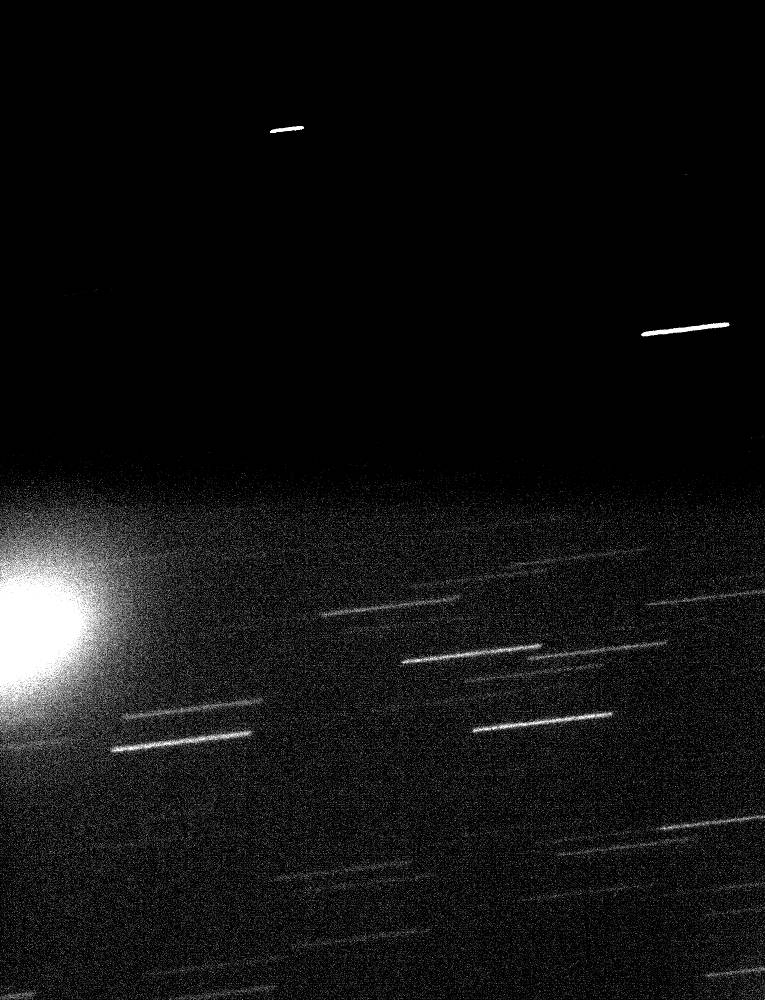
Horizontal stripes:(North-South) example (The stripes are not exact horizontal, but only the orientation of the camera is not correct.) The orientation of the camera is not correct. Take an image with trails with CCDOPS (with shut of telescope drive), rotate the camera, take an image with trails again, until the trails are are be exact vertical. Trails, (39KB) The orientation of an ST-7 must be more exact than 0.11 degree = tan -1(1/lines) (An ST-7 has 510 lines)
Vertical stripes:(West-East) example The read out speed (shiftime) is not correct, this is caused by a wrong declination or a wrong focal length. Fill in the correct focal length and declination at "Settings". The read out speed shout be more exact than 1/510 using a ST-7. It may be useful to take a "stare mode" image and calculate the FL using an astrometry program. The declination must be also known exact, use a known bright star to start. Or you can try to fill in a longer (or shorter) FL until the stars become point like.
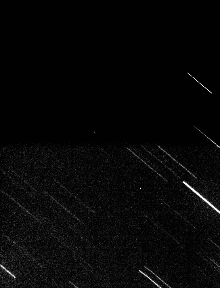
Slanted stripes in the hole image: example The read out speed and the orientation of the camera are not correct.
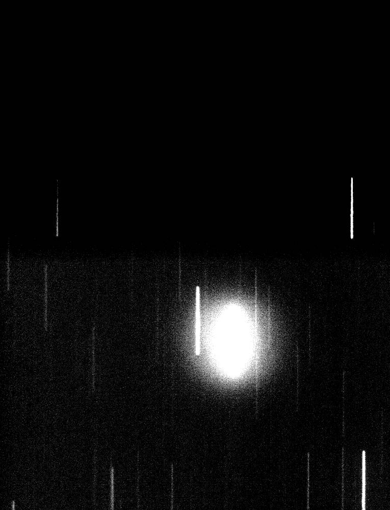
Vertical curved stripes in the hole image: At a high declination the read out speed (shiftime) (declination or focal length) is not correct.
Vertical (curved) stripes at both sides of the image It is taken a image at a high declination. See: differential trailing In most cases the stars at the sides of the image look only a little oval an the image is looking blurred.
Focus: By changing of the temperature during the exposure, the focus can change. Then it should be focused again. Focusing during a drift scan exposure is difficult, better end the exposure and focus using CCDOPS and a "stare mode" image.
Orientation of the camera: If the polar alignment is not exact, the field will rotate by turning the telescope. The orientation of camera has to be adjusted new.
Alt Az mount I have not tested an Alt Az mount. You have to calculate the rotation of the field and adjust the orientation of the camera new for every new Alt Az position, which will be time consuming and difficult ( tolerance about +- 0.11 degree (ST-7),+- 0.056 degree (ST-8)).Using a Alt Az mount as a meridian telescope the orientation of the camera will not change. Focusing the camera will be more difficult. Maybe it can be used a Hartman mask. Or it can be focused on the diffraction spikes. Focusers at dobsons may be difficult to use for CCD imaging. Balancing the scope may be difficult. Adjusting the orientation and the focus the first time may be also difficult.
Accuracy of the timer WinScan uses the clock cycle counter. Pentium (or compartible) is required. (See readme.txt if you want to use SCAN (DOS)). Moving the mouse while taking an image, or running a second program, which requires processor time, should be avoided.(Check the time stamp file, if there are problems). The frequency of the CPU is calculated at the program start of WinScan.
There are problems, when using mobile computers with Intel SpeedStep processors. Better use a computer without a SpeedStep processor. I am not sure, if it is possible to solve this problem by disabling the speed step feature. Anyway, the frequency of the CPU should be calculated at every program start of WinScan, as it may change.
If you need an exact time in the file info (for example to measure positions of minor planets), it is recommend to set the system timer by an internet time server (or an other time source like GPS) every hour. The intern timer of WinScan has to be set to the system timer after that. The intern timer of WinScan can be calibrated, see the help file. Make some tests before starting observations.
Evaluate the image: CCDOPS for Windows can show images up to about 15 MB. You should use ViewScan to view, evaluate and slice the images.
Publishing in the internet: With CCDOPS for Windows or DOS Images can be saved in the TIFF format. This can be changed with a other program to JPG. Even JPG files of drift scan images may to big to be shown by the browser. The images can be rotated clockwise so that east is left and north is at the top. ViewScan can save images or parts of images in JPG format. (and rotate the images before saving as JPG)
Astrometry: The average time at
witch an object is exposed (mid exposure time), is increasing with
every line of the image. (form the west to the east) To calculate the
mid exposure time:
M=S*L - E/2 + T1 ;
M=mid exposure time, S=shiftime (read out rate, time to read out one line), L=line number, E=effective exposure time, T1= time at the start of the image (time, the first line of the file is read out of active array the CCD). This formula is not valid for the ramping at the start (or end, if, after closing the shutter, the rest of the lines are read in) of the image . The shiftime is stored in the file info at the SHIFTIME item. The effective exposure time(E) is calculated (not for the ramping) by: E=Lccd*S
Lccd= lines on the CCD in the current
binning mode, S=shiftime. This formula is not valid for the ramping
at the start (or end) of the image( For the ramping it is: E=L*S/2 )
The effective exposure time (E=Lccd*S) is stored in the file info at
Exposure = 80.123 Using the effective exposure time and the shiftime,
the number of lines of the CCD in the current binning can be
calculated: Lccd=E/S To run SCAN >=1.6 under Windows, use the clock cycle counter
(Pentium only) (Settings(33)).
The orientation of the image is exact in declination, even if the orientation of the camera is not exact. If the orientation of the camera in not exact, there are >=3 reference stars necessary. If the orientation is exact, it will be needed only 2 reference stars.(theoretical). The kind of projection IMHO is a cylindrical projection, but if the orientation of the camera is not exact,IMHO the angle between Rae und Dec is not exact 90 º.
Precession: A drift scan image (fixed telescope), proceeds at a
constant Dec related to the apparent position of the current epoch.
The coordinates of the catalog files of the reference stars are
related to J2000. Related to J2000 there will be a shift in Dec (a
few arc sec.). This is caused by the precession (and nutation and aberration).
So if you slice a
large drift scan image to smaller files, the Dec (J2000) of the
center of the slices will shift slightly from slice to slice. The
orientation of the image may differ from 90 ° because of this.
But there should be no problems, measuring slices in a moderate
height (<1000 pixels).
In very large images (some hours), the plate to sky function
is also affected precession, nutation and aberration.
Evaluate the images: Common astrometry programs may not work with very big drift scan files. Use ViewScan to slice the files. You can also crop parts of the image using CCDOPS. You can also use JimsSlice
, a program written by James Roe to slice drift scan images (SBIG file format only). (That program calculates the time of the begin of the sliced image new, regarding on the shiftime). I wrote a program to view, evaluate and slice drift scan images, you may test a preliminary version of ViewScan(Win 95,98,ME). You may use ViewScan to slice the images and evaluate the slices using other programs. The new version of Charon
will accept drift scan images and also takes care at the shiftime
/mid exposure time. See Settings in Charon for
drift scan images . PinPoint also will accept the slices from ViewScan and correct the mid exposure time.(check the ViewScan help file:"Slice images for PinPoint") You can take 3 images of the same part of the sky, separated by about 0.5 hours. Open the images in ViewScan. Identify one reference star in every image. Add the images to the image list in ViewScan and slice them. The slices can be evaluated by PinPoint and asteroids or supernovae should be found automatically. It is recommend to use two computers, on to take the images, and a second to evaluate them.
Calibrating images: Images can be calibrated on a per line basis using ViewScan. There are no hot pixels in drift scan images, hot pixels are smeared to hot columns. Darks and flats are one dimensional. IMHO calibrating images is not as important for drift scan images as it is for stare mode images.
Errors in positions
in RA and DEC probable caused by atmospheric fluctuations A
preliminary test. Drift scan images should be sliced to slices with a
moderate height.
There may be also systematic errors in the RA positions, caused by a
Charge Transfer Efficiency (CTE) problem.
For more information's on CTE and positional fluctuations caused by the atmosphere see:
Carlsberg Meridian Catalogue 12
especially:
documentation for CMC 12 (4.86 MB)
Others: If clouds pass during the exposure, the brightness of background will be different at different parts of the image.
Using WinScan or SCAN for observing occultation's: Some observers are observing occultation's of
stars by asteroids with standard software, at shut of telescope
drive, letting the stars drift over the CCD, so there are trails of
the stars in the image, and the occultation of a star can be detected
It may be also possible, to let the telescope drive on, the
telescope follows the stars, and the CCD is read out line after line,
using SCAN, so there are also trails in the image. See:
Occultation's
It may be also possible to use that technique to observe lunar occultation's and measure the stellar diameter by the diffraction pattern.
see: CCD
drift-scan imaging lunar occultation's Octavi Fors
Observing
Lunar Occultation's with CCD´s by drift-scan imaging Joan
Genebriera
Other applications for SCAN :
It
should be possible to use a technique, like that mentioned in
observing occultation's, to observe flare stars.
It can be also
evaluated the size and frequency of the seeing with that technique.
Using WinScan or SCAN to take speckle images: WinScan can be used to take speckle images.(of double stars or so) Principe: It is used the tracking CCD and the planetary mode. The shutter is opened, after about 0.03 sec there are read out about 10 lines very fast, the readouttime for one line is about 0.001 sec, this is repeated many times. You will get an image with many sub frames. There is some streaking visible, but the streaking can be removed.
For details
see: speckle.txt
WinScan offers a "sub
array image" feature. The height of the image in that mode is
limited by the height of the CCD, but there is less smearing. Check
the help file of WinScan for that.
see also:
Drift-Mode
CCD readout Users' Manual ( High/Low smear drift mode- speckle
images - sub array images)
Download: Software, to take drift scan images and to view them.
Help file form WinScan, html online version.
This side is still under construction.
updated:
istop
h Flohr Christoph Florh drift scan imaging tdi CCD scan WinScan TDI w